| Brief Description | |
|---|---|
|
Files: \examples\Processing\ObjectFeatures\PrintInspection\PrintInspection_Blob.vad |
 |
|
Default Platform: imaFlex CXP-12 Quad |
|
|
Short Description Blob based position correction and defect detection |
|
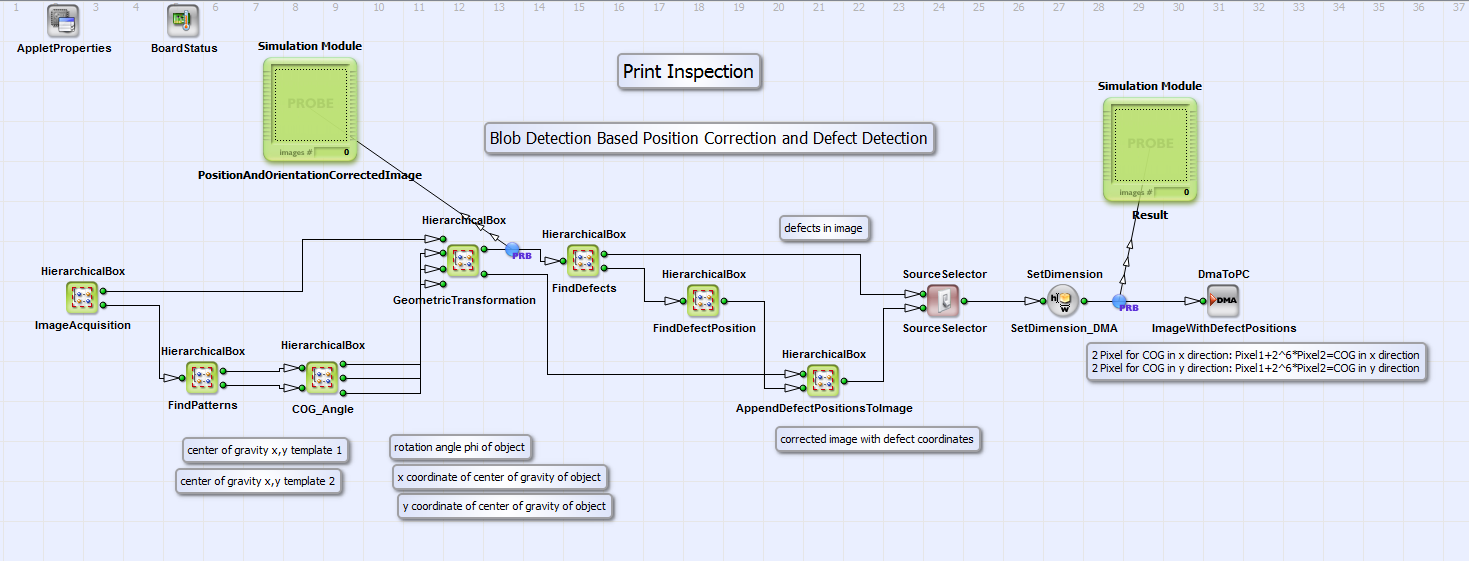
A position and orientation correction of an object and subsequent defect detection in an image is performed in the design "PrintInspection_Blob.vad". The example is suitable for objects with at least two imprints, which maybe used as templates. A special imprint should only occur once on the object. In the example image "TestImage.tif" the letters "K" and "g" are selected as template 1 and 2 with a size of 29x38 pixels. In the comment box on the top layer of the design the single steps to adapt the design to your example image are described. In the design the position and orientation of an object is determined with the blob detection based recognition of two templates on the object. From the coordinates of the two templates the center of gravity of the object is calculated. From the relative position of template 1 and 2 the rotation angle Phi of the object is calculated. With these informations a geometric transformation as described under is performed. The implementation of this transformation is equivalent to the design example "Geometric Transformation_ImageMoments.va" described under . Defects on the position and orientation corrected object are found in subtracting a "golden master" template of the object from the calculated corrected object. What remains are possible defects. Via blob detection the positions of these defects are determined and attached to the image of the position and orientation corrected object. The user can choose whether he/she wants to transfer the image with defects or the image with the position corrected object and the attached defect positions to PC. In the following the basic design structure and the functionality of the single modules are explained. In Fig. 378 you can see the basic design structure.
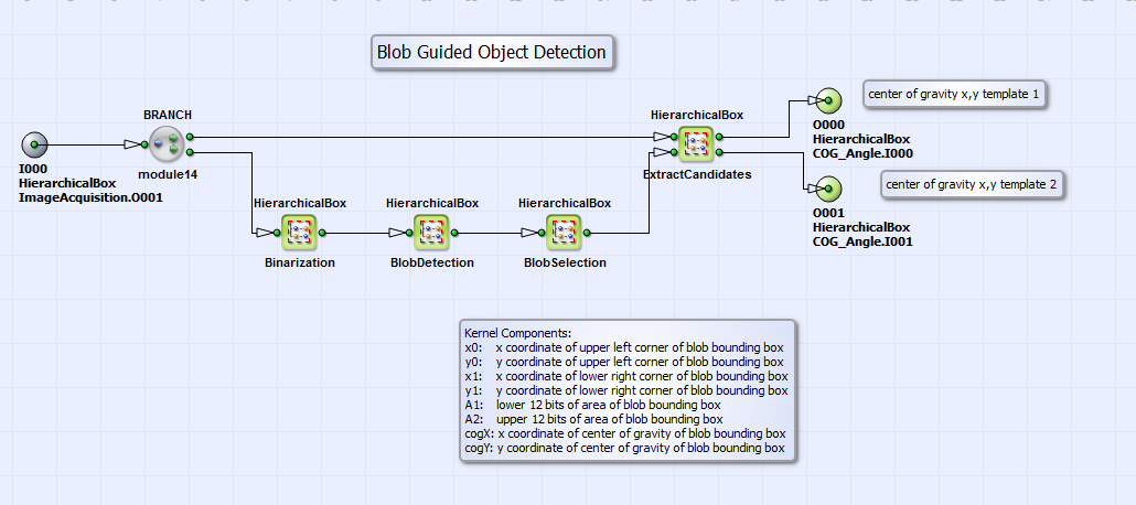
In the HierarchicalBox FindPatterns (see Fig. 379) the acquired image (from box ImageAcquisition) is binarized in the HierarchicalBox Binarization with a simple threshold. When you change the example image you may adjust this threshold to your image. In the HierarchicalBox BlobDetection objects in the binarized image are detected with the operator Blob_Analysis_2D. Output of this operator are the x and y coordinates and the area of a bounding box around each object found. In the comment box in the design you find more detailed information on these parameters. The objects found are then selected in the box BlobSelection with respect to their size and position. Only the coordinate and size informations for the template relevant objects remain. Please adjust the parameters IS_InRange for the valid size and position of the objects to your templates (right-mouse-click on box FindPatterns). The coordinate and size informations are input for the HierarchicalBox ExtractCandidates. See its content in Fig. 380.
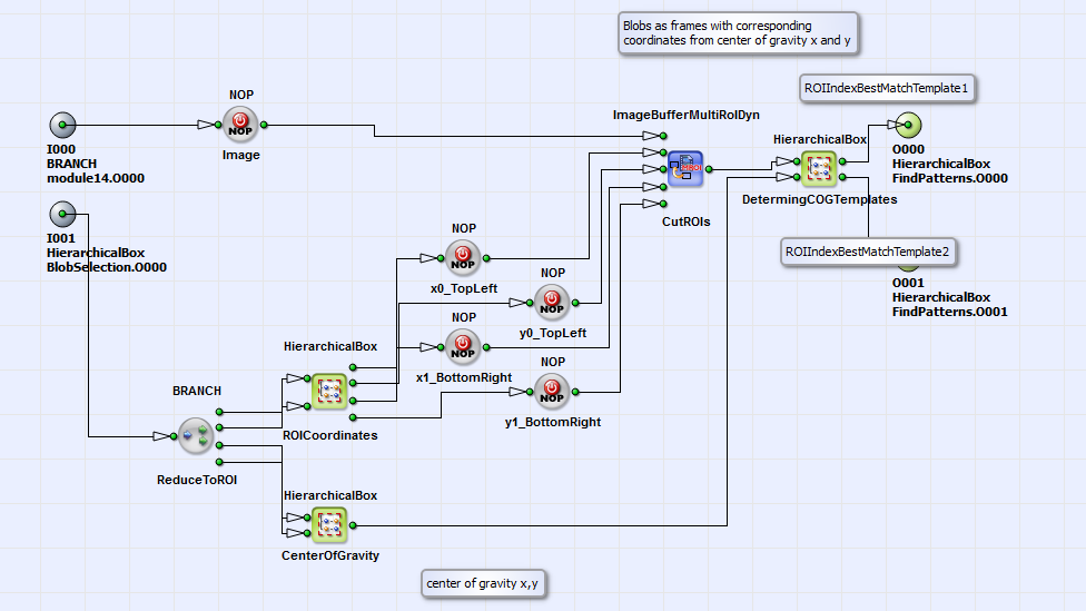
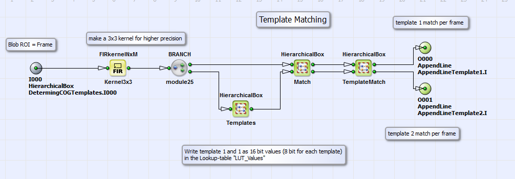
Here each object (detected with blob analysis) is cut from the original image as region of interest with the operator ImageBufferMultiROIDyn_CutROIs and is forwarded as single frame. In the HierarchicalBox DeterminingCOGTemplates (see Fig. 381) the template matching and the subsequent determination of their coordinates in the image is performed.
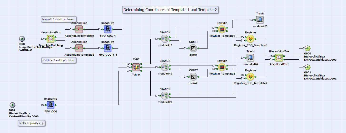
In the box TemplateMatching (see its content in Fig. 382) the matching of the selected objects with template 1 and 2 (letters "K" and "g" with a size of 29x38 pixels) is performed. In Templates template 1 and 2 are written as 16 bit values (8 bit for each template) to the lookup table LUT_Values. The matching of the objects found in the image with template 1 and 2 is the performed as simple 3x3 kernel subtraction in the box Match. In TemplateMatch the kernel component which gives the best match is selected. Going back to the content of DeterminingCOGTemplates, the best template match is selected with the operators RowMin_Template1 and RowMin_Template2 and the corresponding coordinates of template 1 and 2 with the registers Register_COG_Template1, Register_COG_Template2 and the selection of the last pixel in box SelectLastPixel. The output of the box DeterminingCOGTemplates are the coordinates of template 1 and 2.
Going back to the basic design structure we will now have a look in the HierarchicalBox COG_Angle, in which the coordinates of the center of gravity of the object and its rotation angle is determined from the coordinates of template 1 and 2. See the content of COG_Angle in Fig. 383.
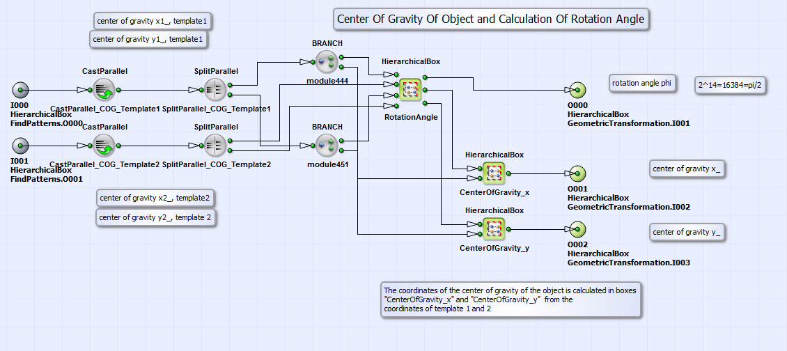
The rotation angle  of the object is calculated in box
RotationAngle according to
of the object is calculated in box
RotationAngle according to
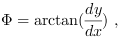
where  are the differences of the coordinates of template 1 and 2
in x and y direction.
are the differences of the coordinates of template 1 and 2
in x and y direction.
The coordinates of the center of gravity of the object  are calculated according to
to
are calculated according to
to
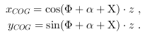
Here  is the angle between the center of gravity of the object, template 1 and
template2,
is the angle between the center of gravity of the object, template 1 and
template2,
 is the angle between template2, template 1 and a horizontal line, when the object
is not rotated and
is the angle between template2, template 1 and a horizontal line, when the object
is not rotated and
 is the distance between the center of gravity of the object and template 1.
When you change the example image you have to adapt these values with right-mouse-click on the box COG_Angle under "properties".
is the distance between the center of gravity of the object and template 1.
When you change the example image you have to adapt these values with right-mouse-click on the box COG_Angle under "properties".
With these information about  ,
,
 the geometric transformation is performed in
box GeometricTransformation" (see basic design structure in Fig. 378) equivalent
to the VA example "GeometricTransformation_ImageMoments.va" described in section .
the geometric transformation is performed in
box GeometricTransformation" (see basic design structure in Fig. 378) equivalent
to the VA example "GeometricTransformation_ImageMoments.va" described in section .
Possible defects in the position and orientation corrected image as output of box GeometricTransformation are found in box FindDefects, where a "golden master" template of the image is subtracted from the processed image. After elimination of remains (a result of bilinear interpolation after geometric transformation) the output of the box FindDefects are the pure defects found on the object. Via blob analysis in box FindDefectPosition with the operator Blob_Analysis_2D the coordinates of these defects are determined. In the box AppendDefectPositionsToImage these coordinates are appended to the position and orientation corrected image. The user can choose whether he/she wants to send the image with pure defects or the corrected image with defect coordinates via DMA to PC in setting the parameter "SelectSource" of the operator SourceSelector to 0 or 1.
